This guide takes the frame from a bag of parts to the complete airframe shown below. It is built in two stages: three sub-assemblies you make first (the landing-gear legs, the motor arms and the payload rail), and then a main-frame stage where everything bolts to the carbon main plate. The whole build is M3 screws, lock nuts and printed fittings. There is nothing to glue.
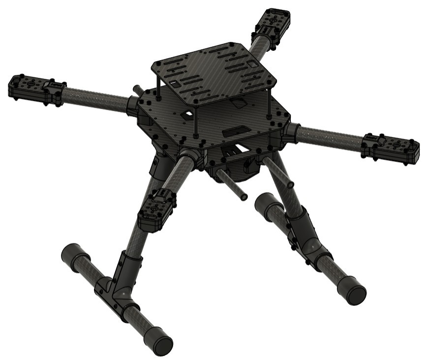
#The build at a glance
| Step | What you do |
|---|---|
| 1 | Landing-gear legs: make 2 |
| 2 | Motor arms: make 4 |
| 3 | Payload rail: make 1 |
| 4 | Leg sockets and legs onto the main plate |
| 5 | Standoffs and top plate |
| 6 | Payload rail onto the main plate |
| 7 | Arm mounts and arms: fit 4 |
| 8 | Final checks |
#Fastener rules
These apply to every step.
- Every screw is M3, and every one is a socket-head cap screw. Only the length changes from step to step, so sort the hardware by length before you begin. Some screws are drawn with domed heads in the pictures; ignore that, they are all socket heads.
- Every nut is an M3 nylon-insert lock nut. The only screws that don't take a nut are the eight M3 × 12 screws in Step 5, which thread into the standoffs.
- Snug, not tight. Carbon-fibre plates crack and tubes crush if you overtighten. Run each lock nut down until the nylon collar engages, then tighten until the parts are just firmly together. The lock nut does the rest.
- Tighten in pairs and diagonals. Wherever a fitting has four screws, take them all to finger-tight first, then snug them in a cross pattern so the fitting pulls down evenly.
- Through-bolted tubes. The leg T-pieces and the leg sockets are locked to their tubes by a screw that passes right through the fitting and the tube. Push the tube fully home, then rotate it until the cross-holes in the tube line up with the holes in the fitting before you push the screw through.
#Tools
- 2.5 mm hex key or driver (all screws)
- 5.5 mm spanner or nut driver (M3 lock nuts)
- A soft mat or towel to protect the carbon while the frame is upside down
#Reading the pictures
Each step has an exploded view of the parts and hardware for that step. Screws are drawn pulled back along the direction they go in, and the loose nuts are drawn on the side they end up on, so if the nuts are below a part in the picture, that's where they go. The frame views in Steps 4 and 6 are drawn with the frame upside down (legs pointing up) so you can see the underside; the text tells you which way up to work.