Everything now bolts to the main plate. Step 4 is done with the plate upside down on the mat; after that the frame can stand on its own legs for the remaining steps.
#Step 4: Leg sockets and legs onto the main plate
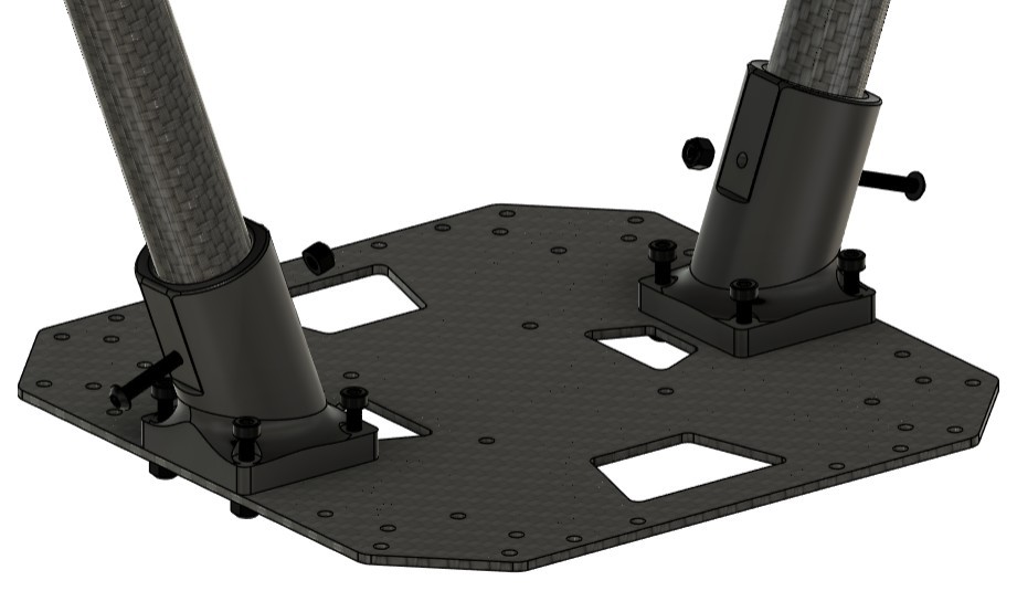
Parts: main plate, 2 leg sockets, and the 2 legs from Step 1.
| Hardware | Per leg | Total (2 legs) |
|---|---|---|
| M3 × 12 socket head | 4 | 8 |
| M3 × 30 socket head | 1 | 2 |
| M3 lock nut | 5 | 10 |
- Lay the main plate on the mat, underside up. The underside is the face the leg sockets and payload rail bolt to; the standoffs and top plate go on the other face.
- Set a leg socket over each of the two leg positions: the four-hole pattern on opposite sides of the plate that matches the socket's flange. The sockets are angled. Turn each one so it leans outward, away from the centre of the plate, so the legs will splay out.
- Bolt each socket down with four M3 × 12 socket heads through the flange, and lock nuts on the other side of the plate. Finger-tight, then snug in a cross pattern.
- Push the upright of one leg into its socket until it bottoms out, and rotate it until the cross-holes near the top of the upright line up with the cross-hole in the socket. The skid should end up running parallel to the nearest edge of the plate.
- Push the M3 × 30 screw through the socket and the upright from the outside, and fit a lock nut on the inside. Snug only.
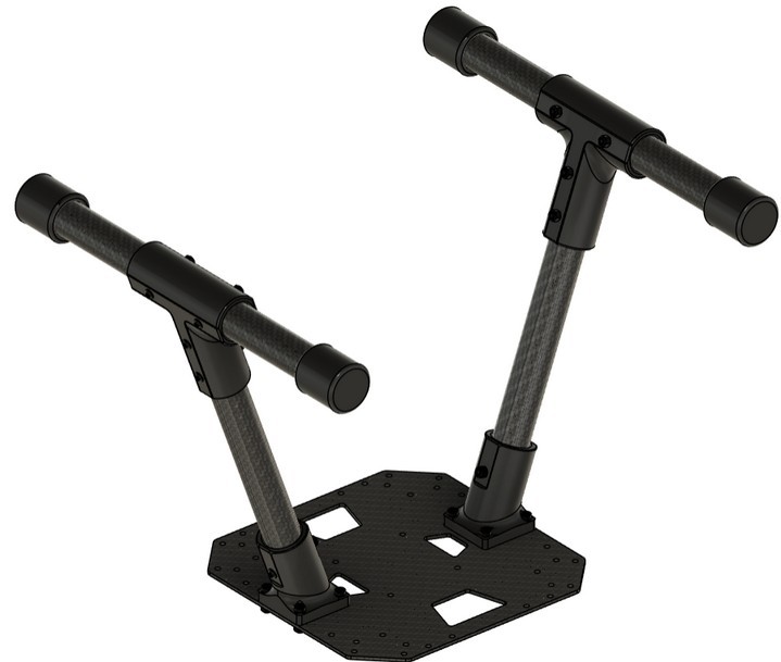
- Fit the second leg the same way. Check that both skids are parallel and the same height.
- Turn the frame over and stand it on its legs. From here on it can stand on its own for the remaining steps.
#Step 5: Standoffs and top plate
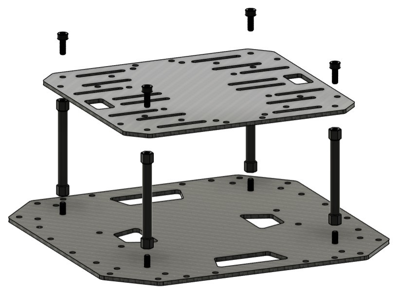
Parts: 4 standoffs, top plate.
| Hardware | Per standoff | Total |
|---|---|---|
| M3 × 12 socket head | 2 | 8 |
| M3 lock nut | none | none |
- Stand the four standoffs on the top face of the main plate at the four inner holes that match the corner holes of the top plate.
- Fix each standoff with an M3 × 12 socket head driven up from the underside of the main plate. Hold the standoff with your fingers so it doesn't spin. These screws thread straight into the standoffs, with no nuts.
- Sit the top plate on the standoffs and fix it with the other four M3 × 12 socket heads from above. Snug is enough.
Tip
Step 6 puts eight lock nuts on the top face of the main plate, directly under the top plate. There is room to get a spanner in between the plates, but if you'd rather have the top face clear, fit only the standoffs now and add the top plate as the very last step.
#Step 6: Payload rail onto the main plate
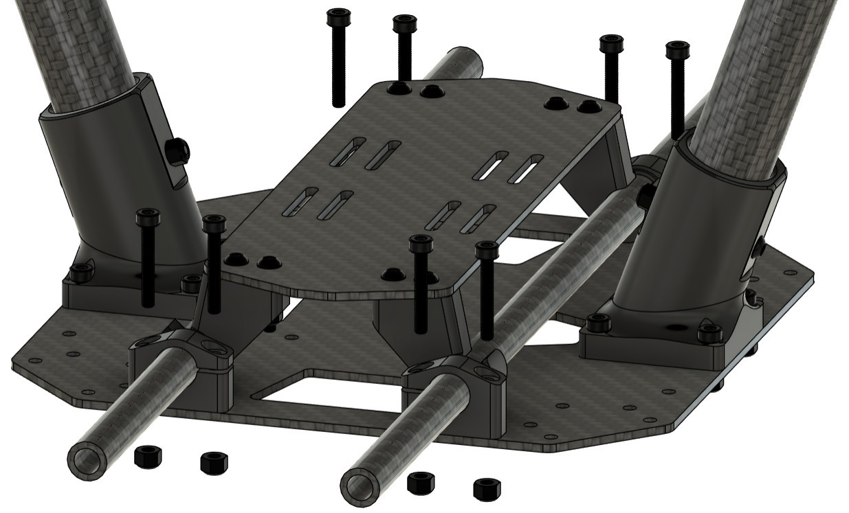
Parts: the payload rail from Step 3.
| Hardware | Per corner | Total |
|---|---|---|
| M3 × 20 socket head | 2 | 8 |
| M3 lock nut | 2 | 8 |
- Turn the rail over so the rods face upward toward the frame, and offer it up to the underside of the main plate, centred, with the rods running front to back (parallel to the skids). The rods end up between the rail plate and the main plate, and the rail plate is the lowest part of the frame.
- Line up the two holes at each corner of the rail plate with the matching holes in the main plate.
- Push the eight M3 × 20 socket heads up through the rail plate and the main plate, so the heads stay on the rail plate, and fit a lock nut to each on the top face of the main plate.
- Take all eight to finger-tight, check the rail is square to the frame, then snug them evenly.
Tip
Push all eight screws through the rail plate first and hold them there with a strip of tape over the heads. You can then offer the whole rail up with one hand and start the nuts with the other.
#Step 7: Arm mounts and arms (fit 4)
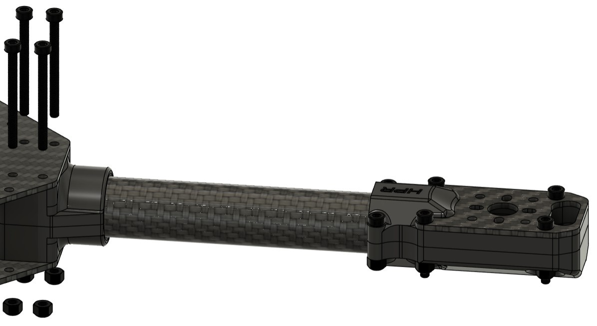
Parts: 4 arm mounts, and the 4 motor arms from Step 2.
| Hardware | Per arm | Total (4 arms) |
|---|---|---|
| M3 × 35 socket head | 4 | 16 |
| M3 lock nut | 4 | 16 |
- Drop four M3 × 35 socket heads down through the four holes at one corner of the main plate.
- Push an arm mount up onto the screw tips from below, with its round socket pointing outward from the corner, away from the centre of the frame. Fit a lock nut to each screw under the mount. Finger-tight, then snug in a cross pattern.
- Push the bare end of a motor arm into the socket until it bottoms out, with the motor plate facing up and level. Make sure it is fully home; the socket is what holds the arm.
- Repeat for the other three corners. Sight across the frame: all four motor plates should be level and at the same height.
Tip
Bolt the mount to the plate before you fit the arm. It is much easier to push the arm home against a mount that is already fixed than to juggle both at once.