Build these three first. They are independent of each other, so the order doesn't matter.
#Step 1: Landing-gear legs (make 2)
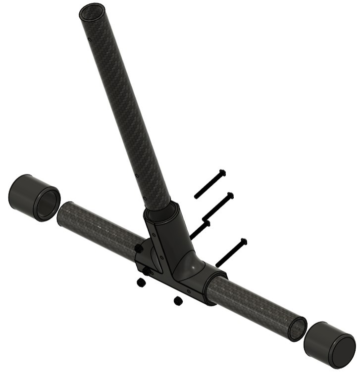
Parts: 1 leg T-piece, 1 upright tube, 1 skid tube, 2 skid end caps, per leg.
| Hardware | Per leg | Total (2 legs) |
|---|---|---|
| M3 × 30 socket head | 4 | 8 |
| M3 lock nut | 4 | 8 |
- Push the upright tube into the round socket of the T-piece until it bottoms out. Rotate the tube until its cross-holes line up with the holes in the socket. The upright has a second set of cross-holes near its free end. Those are for the leg socket in Step 4, so leave that end clear.
- Slide the skid tube through the cross-bore of the T-piece and centre it, with the same length of tube either side of the T. Rotate it until its cross-holes line up with the holes in the T-piece.
- Push the four M3 × 30 screws through the T-piece, passing through the tubes, and fit a lock nut on each on the far side. Tighten until the T-piece grips both tubes firmly, and no further.
- Push an end cap onto each end of the skid tube.
- Build the second leg the same way. The two legs are identical.
#Step 2: Motor arms (make 4)
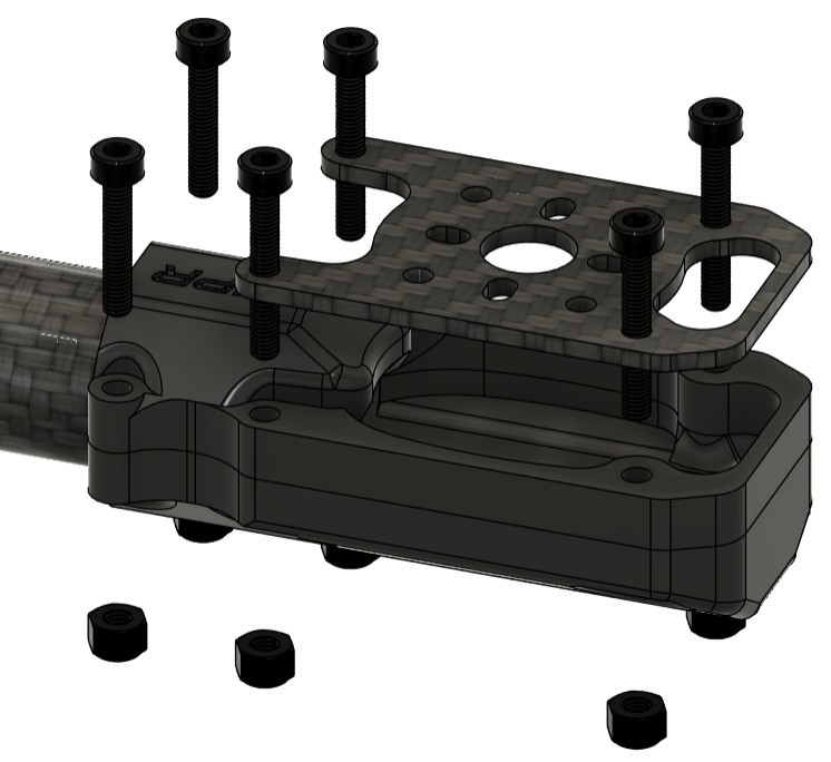
Parts: 1 arm tube, 1 motor mount, 1 motor plate, per arm.
| Hardware | Per arm | Total (4 arms) |
|---|---|---|
| M3 × 18 socket head | 4 | 16 |
| M3 × 16 socket head | 2 | 8 |
| M3 lock nut | 6 | 24 |
- Push one end of the arm tube into the socket of the motor mount until it bottoms out. The other end of the tube stays bare. It goes into the arm mount on the frame in Step 7.
- Sit the motor plate on top of the mount with its holes lined up. The narrow slotted tab on the plate goes at the outer end, away from the arm.
- The mount is taller at the arm end, so the longer screws go there: drop the four M3 × 18 screws through the four holes nearest the arm, and the two M3 × 16 screws through the two holes at the outer end.
- Fit a lock nut to each of the six screws under the mount. Take them all to finger-tight, then snug them in a cross pattern until the plate sits flat on the mount and the arm can't twist in its socket.
- Repeat for the other three arms. All four should be identical.
Tip
If you're going to fit anything in the recess under the motor plate (an ESC, for example), do it now. Once the plate is bolted down the recess is closed.
#Step 3: Payload rail (make 1)
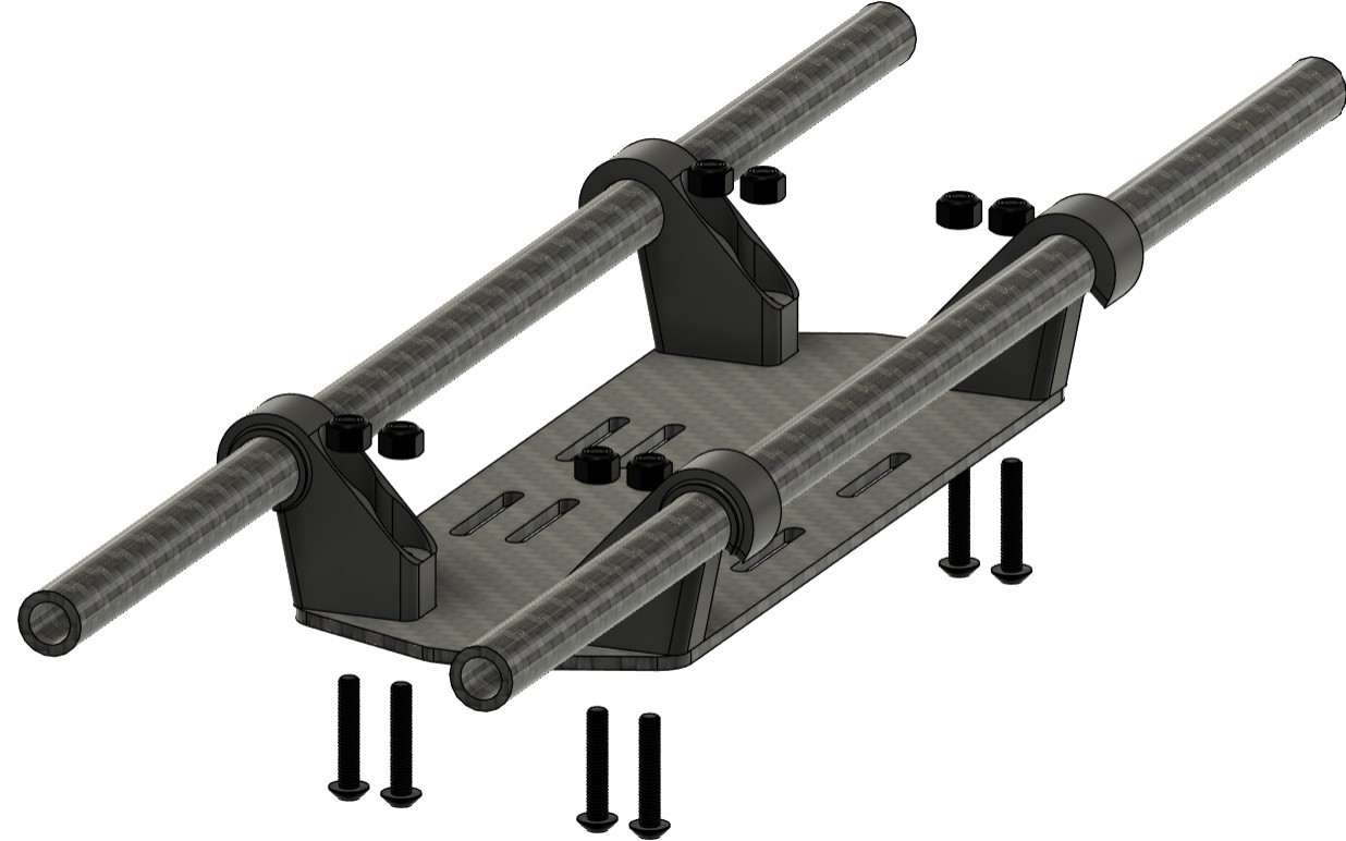
Parts: 1 rail plate, 4 rod clamps, 2 rail rods.
| Hardware | Per clamp | Total (4 clamps) |
|---|---|---|
| M3 × 16 socket head | 2 | 8 |
| M3 lock nut | 2 | 8 |
- Set the four rod clamps on the top face of the rail plate, one at each corner, with their saddles facing up and their screw holes over the holes in the plate. The two clamps on each side must face the same way so their saddles line up.
- Push two M3 × 16 screws up through the plate into each clamp from underneath, and fit a lock nut on top of each. Leave them a turn loose for now.
- Push a rod into the saddles of the two clamps on each side. Set both rods so they overhang the plate by the same amount at each end, or wherever your payload needs them.
- Square everything up so the rods are parallel and the clamps sit flat, then tighten all eight nuts.
Note
Remember which face the clamps are on. In Step 6 the whole rail turns over and bolts to the underside of the frame with the rods facing the main plate, so the rail plate becomes the lowest part of the airframe.